

PRODUCTS
CMC-PLC-5000 Marine Programmable Logic Controller
CMC-PLC-5000 Marine Programmable Logic Controller includes: controller, I/O module, communication module, and signal board; Equipped with dedicated high-speed processor chips, Support IEC61131-3 standard language configuration development, Ethernet, serial bus, CAN bus and other commonly used communication protocols. it is used for centralized collection, transmission, fieldbus communication of various types information in fields such as ships and automation. Through programmable embedded programming, it achieves control functions such as data acquisition, logic calculation, and safety monitoring.
Key words:
Category:
Product Center

Support hotline:
CMC-PLC-5000 Marine Programmable Logic Controller
Graphic details
Product introduction
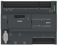
CMC-PLC-5000 Marine Programmable Logic Controller includes: controller, I/O module, communication module, and signal board; Equipped with dedicated high-speed processor chips, Support IEC61131-3 standard language configuration development, Ethernet, serial bus, CAN bus and other commonly used communication protocols. it is used for centralized collection, transmission, fieldbus communication of various types information in fields such as ships and automation. Through programmable embedded programming, it achieves control functions such as data acquisition, logic calculation, and safety monitoring.
Product function

- Support up to 16 tasks and 1ms tasks
- Support up to 200KHz 4-channel high count pulse output, 6 channels of 200KHz high-speed counting and the main control DI support up to 1MHz pulse capture
- Support expansion of 1 signal board+8 IO modules
- Two Ethernet interfaces can form a simple switch network, support Modbus TCP protocol and redundant configuration of two Ethernet channels
- One RS485 interface can simultaneously connect third-party devices and HMI touch screens, supporting Modbus RTU/PROFIBUS-DP/free port communication
- Support for extended thermal resistance and hotspot couple signal acquisition, CAN2.0 and RTU communication
- Adopting the same outgoing method as Siemens S7-Smart200, facilitating the replacement of existing market.
Product composition
|
Model |
parameter information |
|
|
MC5201 |
Basic indicators |
|
|
Input Voltage |
24VDC (MC5201) |
|
|
Number of supported modules |
8 fully analog modules and 10 fully digital modules |
|
|
hardware configuration |
||
|
CPU |
Industrial grade ARM, up to 800MHz, supporting hard floating point numbers |
|
|
bandwidth |
Control network up to 6Mbps System network 10/100/1000Mbps |
|
|
physical layer |
Control network RS485 half duplex System network RJ45 electrical port |
|
|
communication protocol |
UDP protocol (multicast, peer-to-peer) Modbus TCP protocol |
|
|
CM5201 |
Basic indicators |
|
|
Power supply parameters |
5VDC±10%(System side power supply)
|
|
|
consumption |
<1W(System side power consumption) |
|
|
function |
Communication module, expanding serial communication capability |
|
|
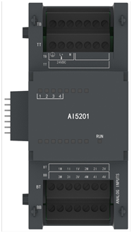
AI5201 |
Basic indicators |
|
|
Power supply parameters |
5VDC±10%(System side power supply) 24VDC±10%(On site power supply)
|
|
|
consumption |
<1W(System side power supply) <5W(On site power supply) |
|
|
Basic indicators |
||
|
Number of input channels |
4 |
|
|
signal type |
At current input: 0-20mA is the effective signal input range Short line break detection is not supported during 0-4mA acquisition At voltage input: -10V~10V is the effective signal input range |
|
|
initialization time |
<10s |
|
|
accuracy |
≤0.2% F.S@25℃ |
|
|
AI5201 |
Basic indicators |
|
|
Power supply parameters |
5VDC±10%(System side power supply) 24VDC±10%(On site power supply) |
|
|
consumption |
<1W(System side power supply) <5W(On site power supply) |
|
|
Basic indicators |
||
|
Number of output channels |
4 |
|
|
signal type |
0~20mA、-10V~10V |
|
|
initialization time |
<10s |
|
|
accuracy |
≤0.2% F.S@25℃ |
|
|
rated load |
current mode:≤750Ω@20mA; Voltage Mode:≤5mA@(0~10VDC) |
|
|
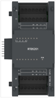
RTD5201 |
Basic indicators |
|
|
Power supply parameters |
5VDC±10%(System side power supply) 24VDC±10%(On site power supply) |
|
|
consumption |
<1W(System side power supply) <5W(On site power supply) |
|
|
Basic indicators |
||
|
Number of input channels |
4 |
|
|
signal type |
Resistance、Pt100、Cu50 |
|
|
initialization time |
<10s |
|
|
accuracy |
≤0.2% F.S@25℃ |
|
|
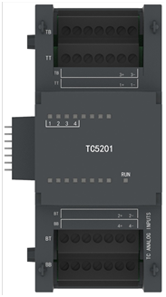
TC5201 |
Basic indicators |
|
|
Power supply parameters |
5VDC±10%(System side power supply) 24VDC±10%(On site power supply) |
|
|
consumption |
<1W(System side power supply) <5W(On site power supply) |
|
|
Basic indicators |
||
|
Number of input channels |
4个 |
|
|
signal type |
mV/E/J/K/S |
|
|
initialization time |
<10s |
|
|
accuracy |
≤0.2% F.S@25℃ |
|
|
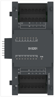
DI5201 |
Basic indicators |
|
|
Power supply parameters |
5VDC±10%(System side power supply) 24VDC±10%(On site power supply) |
|
|
consumption |
<1W(System side power supply) <5W(On site power supply) |
|
|
Basic indicators |
||
|
Number of input channels |
16 channels, both source and drain types supported |
|
|
Switching input |
-3-4.5V: logic "0", 16.5-27V: logic "1"
5.5~13.5V, above 33V: external fault
4.5-5.5V, 13.5-15.5V, 27-33V: transition state |
|
|
Collection cycle |
≤10ms |
|
|
Signal deboubling |
With signal jitter removal, the jitter removal time is 0-20ms |
|
|
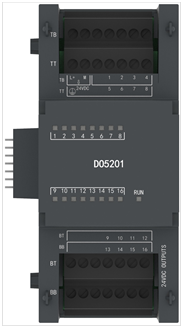
DO5201 |
Basic indicators |
|
|
Power supply parameters |
5VDC±10%(System side power supply) 24VDC±10%(On site power supply) |
|
|
consumption |
<1W(System side power supply) <5W(On site power supply) |
|
|
Basic indicators |
||
|
Channel configuration |
16 channels, 24V active output |
|
|
Switching output characteristics |
load current 0.5A@24V Per channel |
|
|
Collection cycle |
≤10ms |
|
|
Isolation type |
Group isolation, 8 channels per group, a total of 2 groups |
|
|
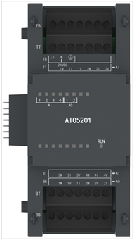
AIO5201 |
Basic indicators |
|
|
Power supply parameters |
5VDC±10%(System side power supply) 24VDC±10%(On site power supply) |
|
|
consumption |
<1W(System side power supply) <3W(On site power supply) |
|
|
Basic indicators |
||
|
Channel configuration |
4 acquisition channels and 2 output channels |
|
|
Signal type |
Input analog quantity: 0-20mA, -10V~10V voltage
Output analog quantity: 0-20mA, -10V~10V voltage |
|
|
Signal range |
Current type analog quantity: 0-20mA is the effective signal input range (short circuit and open circuit detection is not supported at 0-4mA)
Voltage type analog quantity: -10V~10V |
|
|
DIO5201 |
Basic indicators |
|
|
Power supply parameters |
5VDC±10%(System side power supply) 24VDC±10%(On site power supply) |
|
|
consumption |
<1W(System side power supply) <3W(On site power supply) |
|
|
Basic indicators |
||
|
Channel configuration |
8-channel digital input, both source and drain types supported
8-channel digital output, 24V active output |
|
|
Switching input |
-3-4.5V: logic "0", 16.5-27V: logic "1"
5.5~13.5V, above 33V: external fault
4.5-5.5V, 13.5-15.5V, 27-33V: transition state |
|
|
Switching output characteristics |
load current 0.5A@24V Per channel |
|


Previous
Next
CMC-DCS-6000 Series Platform Hardware
MAIN PRODUCTS
FAX:010-56654600
ADD:535JinQiao Road,Pudong District,Shanghai P.R.China (SHANGHAI )
Xinghuo Road 4, Science park,Fengtai District, Beijing P.R.China (BEIJING)
Tel:(+86)010-80339847
E-mail:gxgdb@cssc-cmc.com

Scan to view
the mobile terminal


© Copyright 2022 CSSC MARINE TECHNOLOGY CO.,LTD. All Rights Reserved. 沪ICP备15025664号-2 Powered by www.300.cn seo